Hyundai Genesis (DH): BCM (Body Control Module) / Repair procedures
| Removal |
| 1. |
Disconnect the negative (-) battery terminal. |
| 2. |
Remove the glove box housing.
(Refer to Body - "Glove Box") |
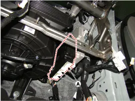
| 3. |
Disconnect the body control module connectors (A).
|
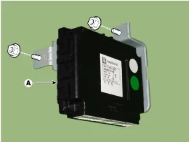
| 4. |
Remove the mounting nuts(2) to loosen the BCM (A).
|
| Installation |
| 1. |
Install the body control module. |
| 2. |
Install the glove box housing. |
| 3. |
Connect the negative(-) battery terminal. |
| BCM Diagnosis With GDS |
| 1. |
In the body electrical system, failure can be quickly diagnosed by using the vehicle diagnostic system (GDS).
The diagnostic system(GDS) provides the following information.
|
| 2. |
Select the 'Car model' and the 'Body Control Module (BCM)' to be checked in order to check the vehicle with the tester. |
| 3. |
Select the 'Current Data' menu to search the current state of the input/output data. |
| 4. |
To forcibly actuate the input value of the module to be checked, select option 'Actuation Test'
|
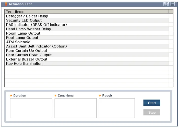
| 5. |
If you want to change user option, select |
Description Body Control Module (BCM) function NOBCM Function1Burglar Alarm2Defroster3Rear Curtain4ATM control5Tail Lamp6H/Lamp Low/High7Welcom/Escort8Auto Light9Passing 10HBA11Front/Rear Fog Lamp12AV Tail13DRL lamp control14Static Bending15Flasher16Room Lamp 17Foot Lamp18Mood Lamp19SSB Ring Illumination2021Panic Alarm22Remote Start23Trunk24SBR25Key Operated Warning26Parking Brake Warning27SMK System Warning28Sun Roof Open Warning29PAS Warning30Front Wiper Low/High31Front Wiper Mist 32Front Wiper Auto33Front Wiper Washer34USM35ECM Mirror36CAN 37LIN Communication Network Diagram AbbreviationExplanationAAFActive Air FlapACUAirbag Control UnitADMAssist Door ModuleAHDActive Hood SystemAMPAmplifierARSArmrest SwitchASCCAdvanced Smart Cruise ControlAVMAround View MonitorAWDAll Wheel DriveB_CANBody Controller Area NetworkBCMBody Control ModuleBSDBlind Spot DetectionC_CANChassis Controller Area NetworkCCPCenter Control PanelCLUMCluster ModuleDATCDual Automatic Temp ControlDDMDriver Door ModuleDisplayDisplay MonitorDSSDriver Seat SwitchECSElectronic Control SuspentionEMSEngine Management SystemEPBElectronic Parking BrakeEVPEva Vacuum PumpFPCMFuel Pump Control ModuleH/UnitHead UnitHSWSHaptic Steering Warning SystemHUDHead Up DisplayI-BOXTelematics SystemIDBIntegrated Dynamic BrakeLDWSLane Departure Warning SystemM_CANMulti media Controller Area NetworkMDPSMotor Driven Power SteeringMFSMulti-Function SwitchODSOccupant Detection SystemP_CANPowertrain Controller Area NetworkPGSParking Guide SystemPSBPre-Safe Seat BeltPSMPower Seat ModulePTLMPower Trunk Lid ModuleRRCRear Remote ControlSASSteering Angle SensorSCMSteering Column ModuleSJBSmart Junction BoxSLBSeat Lumber BolsterSMKSmart Key UnitSPASSmart Parking Assist SystemSWRCSteering Wheel Remote ControllerTCUTransmission Control UnitTPMSTire Pressure Monitoring SystemVDCVehicle Dynamic Control
Other information:
Hyundai Genesis (DH) 2013-2016 Service Manual: Description and Operation
D
Hyundai Genesis (DH) 2013-2016 Service Manual: Condenser Repair procedures
Inspection 1. Check the condenser fins for clogging and damage. If they are clogged, clean them with water, and blow them with compressed air. If they are bent, gently bend them using a screwdriver or pliers. 2. Check the condenser connections for leakage, and repair or replace it, if required.
Categories
- Manuals Home
- Hyundai Genesis Owners Manual
- Hyundai Genesis Service Manual
- Restraint
- Engine Electrical System
- Repair procedures
- New on site
- Most important about car
