Hyundai Genesis (DH): Multifunction Switch / Repair procedures
Hyundai Genesis (DH) 2013-2016 Service Manual / Body Electrical System / Multifunction Switch / Repair procedures
| Removal |
| 1. |
Disconnect the negative (-) battery terminal. |
| 2. |
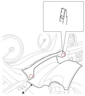
Remove the steering column upper shrouds (A).
(Refer to Body - "Steering Column Shroud Panel")
|
| 3. |
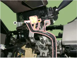
Disconnect the multifunction switch connector (A).
|
| 4. |
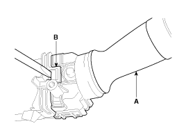
Remove the wiper switch (A) by pushing the lock pin (B).
|

| 5. |
If it is necessary to remove multifunction switch assembly, remove the steering wheel.
(Refer to Steering - "Steering wheel") |
| 6. |
Remove the clock spring.
(Refer to Restraint - "Driver Airbag (DAB) Module and Clock Spring")
|
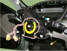
| 7. |
Loosening the screws (2EA) from the multifunction switch assembly (A).
|

| Installation |
| 1. |
Install the multifunction switch. |
| 2. |
Install the clock spring and steering wheel. |
| 3. |
Install the steering column upper and lower shrouds. |
| 4. |
Install the steering wheel. |
| Inspection (With GDS) |
| 1. |
In the body electrical system, failure can be quickly diagnosed by using the vehicle diagnostic system (GDS).
The diagnostic system(GDS) provides the following information.
|
| 2. |
Select the 'Car model' and the 'Multi Function Switch (MFSW)' to be checked in order to check the vehicle with the tester. |
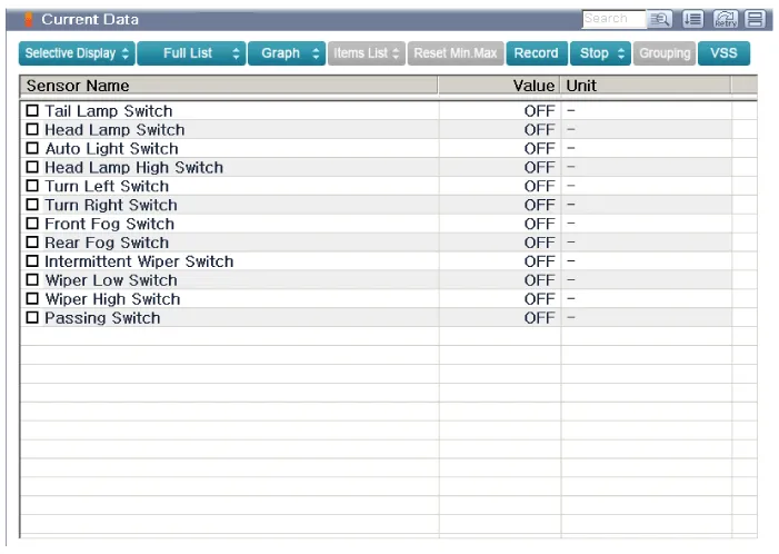
| 3. |
Select the 'Current Data' menu to search the current state of the input/output data.
|
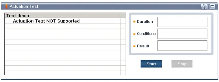
| 4. |
To forcibly actuate the input value of the module to be checked, select option 'Actuation Test'
|
Component 1. Steering column2. Lighting switch3. Wiper switch4. Screw5. Clock Spring
Other information:
Hyundai Genesis (DH) 2013-2016 Service Manual: Condenser Repair procedures
Inspection 1. Check the condenser fins for clogging and damage. If they are clogged, clean them with water, and blow them with compressed air. If they are bent, gently bend them using a screwdriver or pliers. 2. Check the condenser connections for leakage, and repair or replace it, if required.
Hyundai Genesis (DH) 2013-2016 Service Manual: Climate Control Air Filter Repair procedures
Replacement 1. Remove both stoppers (B) by turning them from the glove box (A). 2. Disconnect the air damper (A) from the glove box (B). 3. Remove the filter cover (A) by pressing the knob. 4. Replace the air filter (A) with a new one according to the direction of air filter.
Categories
- Manuals Home
- Hyundai Genesis Owners Manual
- Hyundai Genesis Service Manual
- Repair procedures
- Smart Cruise Control Unit Repair procedures
- Steering System
- New on site
- Most important about car

Copyright © 2026 www.hgenesisdh.com - 0.0212