Hyundai Genesis (DH): Panorama Sunroof / Panorama Sunroof Switch Components and Components Location
| Components |
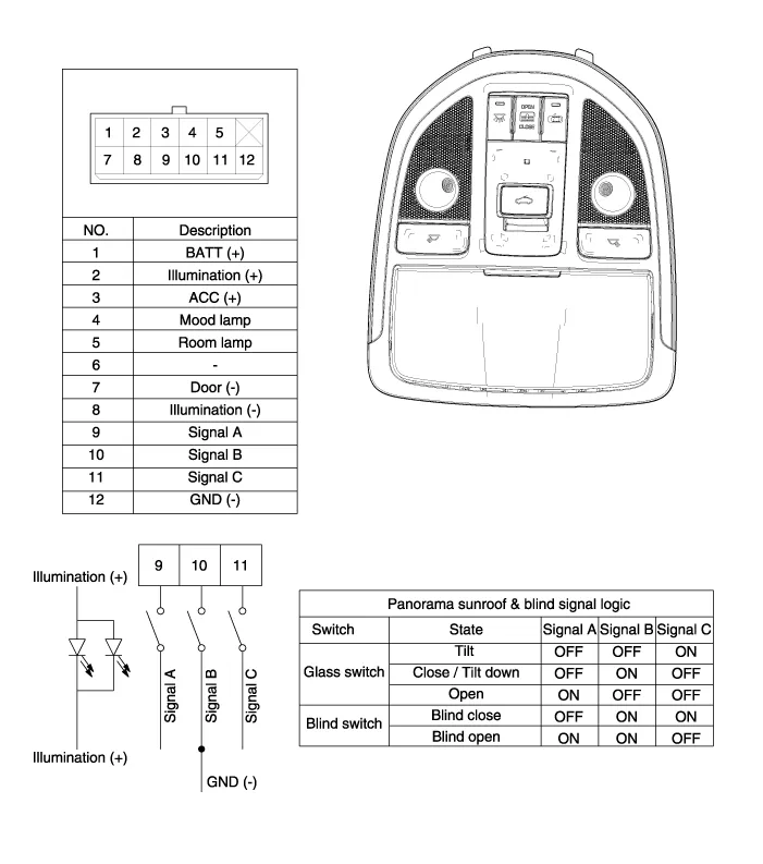
Circuit Diagram NO.Overhead console connector (10pin)Panorama sunroof motor (12pin)Roller blind motor (12pin)1GroundGround 1Battery (+)2-Glass status signal/ Parameter tool-3IGNGNDGround4Signal C switchLIN 1LIN 15Signal A switchLIN2LIN 26Battery (+)Signal B switch-7Glass status signal/ Parameter toolSignal C switch-8Vehicle speed signalSignal A switch-9---10Signal B switch--11?Vehicle speed signal-12IGNIGN
Inspection 1. Disconnect the negative (-) battery terminal. 2. Open the sunglass case cover from the overhead console and remove the 2 screws holding the overhead console.
Other information:
Hyundai Genesis (DH) 2013-2016 Service Manual: Photo Sensor Repair procedures
Inspection 1. Turn the ignition switch ON. 2. Connect the GDS. 3. Emit intensive light toward the photo sensor using a lamp, and check the output voltage change. 4. The voltage will rise with higher intensive light and fall with lower intensive light.
Hyundai Genesis (DH) 2013-2016 Service Manual: Ambient Temperature Sensor Description and Operation
Description The ambient temperature sensor is located inside the side mirror and detects ambient air temperature. It is a negative type thermistor; resistance will increase with lower temperature, and decrease with higher temperature. The sensor output will be used for discharge temperature control, temperature regulation door control,
Categories
- Manuals Home
- Hyundai Genesis Owners Manual
- Hyundai Genesis Service Manual
- Body Electrical System
- Restraint
- Brake System
- New on site
- Most important about car
