Hyundai Genesis (DH): IMS(Integrated Memory System) / Memory power seat switch Repair procedures
Hyundai Genesis (DH) 2013-2016 Service Manual / Body Electrical System / IMS(Integrated Memory System) / Memory power seat switch Repair procedures
| Removal |
| 1. |
Disconnect the negative (-) battery terminal. |
| 2. |
Remove the driver's door trim.
(Refer to Body - "Front Door Trim") |
| 3. |
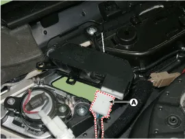
Remove the memory power seat switch connector (A).
|
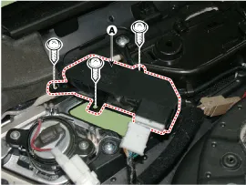
| 4. |
Loosen the mounting screws and remove the memory power seat switch (A).
|
| Installation |
| 1. |
Install the memory power seat control switch (IMA). |
| 2. |
Install the door trim. |
| 3. |
Connect the negative (-) battery terminal. |
| inspection |
| 1. |
Remove the memory power seat connector
|
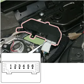
| 2. |
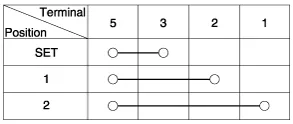
When each switch is pressed, check the electric current
between memory power seat switch connector and grounding, and if the
electricity does not match the specification, replace the switch.
|
Description The Tilt & Telescope operation function in SCM contains of the following function. 1. Manual control with direction switches (Tilt Up/Down, Telescope Forward/Backward).
Other information:
Hyundai Genesis (DH) 2013-2016 Service Manual: Components and Components Location
C
Hyundai Genesis (DH) 2013-2016 Service Manual: Repair procedures
Diagnosis With GDS 1. BSD system defects can be quickly diagnosed with the GDS. GDS operates actuator quickly to monitor, input/output value and self diagnosis. 2. Connect the cable of GDS to the data link connector in driver side crash pad lower panel, and turn on the GDS.
Categories
- Manuals Home
- Hyundai Genesis Owners Manual
- Hyundai Genesis Service Manual
- Emission Control System
- Steering System
- Description and Operation
- New on site
- Most important about car

Copyright © 2026 www.hgenesisdh.com - 0.0256