Hyundai Genesis (DH): Fuel Delivery System / Fuel Pump Control Module (FPCM) Repair procedures
Hyundai Genesis (DH) 2013-2016 Service Manual / Engine Control / Fuel System / Fuel Delivery System / Fuel Pump Control Module (FPCM) Repair procedures
| Inspection |
| 1. |
Connect the GDS on the Data Link Connector (DLC). |
| 2. |
If there is DTC on the GDS, replace the FPCM. |
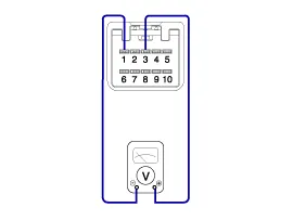
| 3. |
Check the output voltage of fuel pressure sensor (FPS).
|
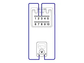
| 4. |
Check the output voltage of fuel pressure sensor (FPS) at idle.
|
| 5. |
Test the lower fuel pressure line.
(Refer to Fuel Delivery System - "Fuel Pressure Test")
|
| Removal |
| 1. |
Turn the ignition switch OFF and disconnect the battery negative (-) cable. |
| 2. |
Remove the trunk rear transverse trim. |
| 3. |
Fold the luggage side trim (LH). |
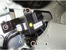
| 4. |
Disconnect the fuel pump control module connector (A). |
| 5. |
Remove the mounting nuts (B), and then remove the fuel pump control module (C) from the vehicle.
|
| Installation |
| 1. |
To install, reverse the removal procedure. |
Circuit Diagram
Description The fuel pressure sensor (FPS) is installed on top of the low pressure fuel pump and measures the pressure of the low pressure fuel line.
Categories
- Manuals Home
- Hyundai Genesis Owners Manual
- Hyundai Genesis Service Manual
- Body Electrical System
- Repair procedures
- Brake System
- New on site
- Most important about car

Copyright © 2026 www.hgenesisdh.com - 0.0205