Hyundai Genesis (DH): Front Suspension System / Front Strut Assembly Repair procedures
Hyundai Genesis (DH) 2013-2016 Service Manual / Suspension System / Front Suspension System / Front Strut Assembly Repair procedures
| Removal |
| 1. |
Loosen the wheel nuts slightly. Raise the vehicle, and make sure it is securely supported. |
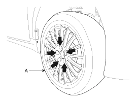
| 2. |
Remove the front wheel and tire (A) from the front hub.
|

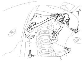
| 3. |
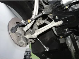
Using a hex wrench, fix the end of stabilizer link and then loosen the nut(A).
[ECS]
[HPD]
|
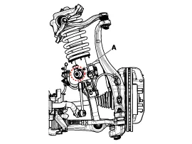
| 4. |
Loosen the bolt & nut (A), separate the front shock absorber assembly from the lower arm.
[4WD]
[2WD]
|
| 5. |
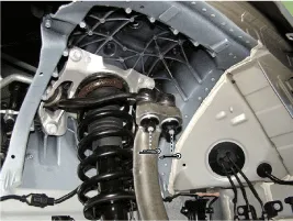
Disconnect the connector and loosen the wheel speed sensor bracket bolt to remove it. [ECS]
|

| 6. |
Loosen the wheel speed sensor bracket bolt to remove it. [HPD]
|
| 7. |
Remove the split pin & castle nut.
|
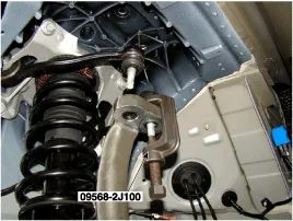
| 8. |
Disconnect the front upper arm from the knuckle using a SST (09568-2J100).
|
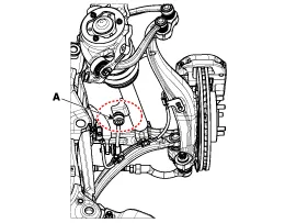
| 9. |
Disconnect the front strut assembly from the frame by loosening the mounting bolt (A).
|
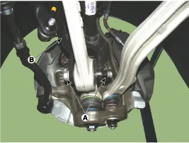
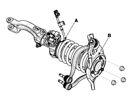
| 10. |
Loosen the nuts and remove the bracket (B) from the strut assembly (A).
|
| 11. |
Install in the reverse order of removal. |
| 12. |
Check the alignment.
(Refer to Tires/Wheels - "Alignment")
|
| Disassembly |
| 1. |
Compress the coil spring with a strut spring compressor. Do not compress the spring excessively. |
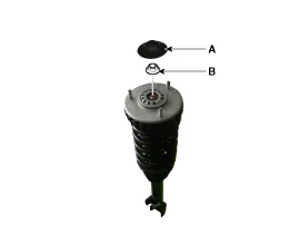
| 2. |
Remove the lock nut (B) after removing the cover (A).
|
| 3. |
Gradually turn the bolt on the spring compressor to slowly
release the tension from the spring. Then, disconnect the components. |
| 4. |
Reassembly is in the reverse order of disassembly.
|

