| Removal |
| 1. |
Loosen the wheel nuts slightly. Raise the vehicle, and make sure it is securely supported. |
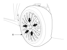
| 2. |
Remove the front wheel and tire (A) from the front hub.
|
| 3. |
Remove the brake caliper assembly.
(Refer to Brake System - "Front Disc Brake") |
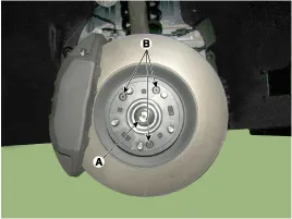
| 4. |
Loosen the driveshaft caulking nut (A) and then remove the brake disc by loosening the screw (B-3EA).
|
| 5. |
Remove the wheel speed sensor by loosening the wheel speed sensor bracket bolt (A) and wheel speed sensor mounting bolt (B).
|
| 6. |
Remove the tie rod end ball joint from the knuckle.
|
| 7. |
Using the special tool (09568-2J100), remove the compression arm from the knuckle.
|
| 8. |
Loosen the nut and using the special tool (09568-2J100), remove the lateral arm from the knuckle.
|
| 9. |
Using the special tool (09568-2J100), remove the upper arm from the knuckle and then separate the kuckle assembly.
|
| 10. |
Using a plastic hammer, disconnect driveshaft (A) from the axle hub (B).
|
| 11. |
Loosen the drive belt. [LAMBDA]
(Refer to Engine Mechanical System - "Timing System") |
| 12. |
Remove the compressor and fix other components surrounding the compressor with wire. [LAMBDA]
(Refer to Heating, Ventilation, Air Conditioning - "Compressor") |
| 13. |
Remove the driveshaft(LH) by loosening the mounting bolt(A).
[LAMMDA]
[TAU]
|
| 14. |
Insert a pry bar between the transaxle case and joint case, and separate the drive shaft from the transaxle case.[RH] |
| 15. |
Install in the reverse order of removal.
|
| 16. |
Check the front alignment.
(Refer to Suspension System - "Front Alignment") |
Front Driveshaft Components and Components Location