
Hyundai Genesis (DH): Motor Driven Power Steering / Description and Operation
Hyundai Genesis (DH) 2013-2016 Service Manual / Steering System / Motor Driven Power Steering / Description and Operation
| Description |
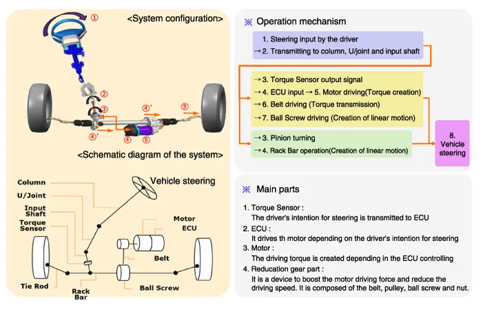
MDPS (Electric power steering, Column assist type) system
uses an electric motor to assist the steering force and it is an engine
operation independent steering system. MDPS control module controls the
motor operation according to information received from the each sensor
and CAN (Controller Area Network), resulting in a more precise and
timely control of steering assist than conventional engine-driven
hydraulic systems. Components (Torque Sensor, Fail-safe relay, etc.) of
the MDPS system are located inside the steering column & MDPS unit
assembly and the steering column & MDPS unit assembly must not be
disassemble to inspect or replace them.
| Operation |
R-MDPS operation mechanism
Circuit Diagram 1. Connector terminal TypePin NoDescriptionBattery1Battery -2Battery +Vhicle1-2-3-4-5-6-7IGN8High_CAN9Low_CAN10-11-12- 2. Circuit Diagram
Other information:
Hyundai Genesis (DH) 2013-2016 Service Manual: LKAS Unit Repair procedures
Removal 1. Disconnect the negative (-) battery terminal. 2. Remove the mirror wiring cover (A) and rain sensor cover (B). 3. Remove the LKAS unit connector (A). 4. Remove the LKAS unit after disengaging the mounting bracket (A). Installation 1.
Hyundai Genesis (DH) 2013-2016 Service Manual: Console Temperature Control Actuator Repair procedures
Inspection 1. Turn the ignition switch OFF. 2. Disconnect the console temperature control actuator connector. 3. Verify that the console temperature control actuator operates to the defrost mode when connecting 12V to terminal 3 and grounding terminal 4.
Categories
- Manuals Home
- Hyundai Genesis Owners Manual
- Hyundai Genesis Service Manual
- Evaporative Emission Control System
- Transmission Control Module (TCM) Repair procedures
- General Information
- New on site
- Most important about car

Copyright В© 2026 www.hgenesisdh.com - 0.025