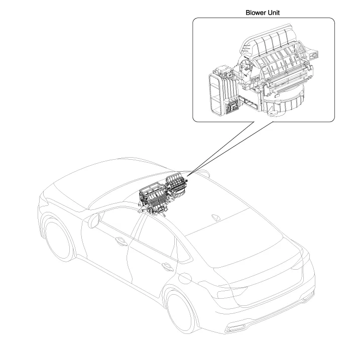
Hyundai Genesis (DH): Blower / Blower Unit Components and Components Location
| Component Location |
| Components |
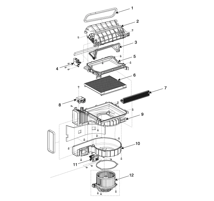
| 1. Seal 2. Intake Duct Case 3. Intake Door 4. Intake Actuator 5. Intake Duct Case (A) 6. Climate Control Air Filter | 7. Climate Control Air Filter Cover 8. Cluster Ionizer 9. Blower Upper Case 10. Blower Lower Case 11. Power Mosfet 12. Blower Motor |
Replacement 1. Disconnect the negative (-) battery terminal. 2. Recover the refrigerant with a recovery/recycling/charging station. 3. When the engine cools down, drain the engine coolant from the radiator.
Other information:
Hyundai Genesis (DH) 2013-2016 Service Manual: Rheostat Repair procedures
Inspection 1. Disconnect the negative (-) battery terminal. 2. Remove the crash pad lower panel. (Refer to Body - "Crash Pad Lower Panel") 3. Remove the lower crash pad switch assembly (A) after disengaging the mounting clip. 4. Remove the rheostat switch connector (A).
Hyundai Genesis (DH) 2013-2016 Service Manual: Auto Defogging Actuator Repair procedures
Inspection 1. Turn the ignition switch OFF. 2. Disconnect the auto defogging connector. 3. Verify that the auto defogging actuator operates to the open position when connecting 12V to terminal 3 and grounding terminal 4. Verify that the auto defogging actuator operates to the close position when connected in reverse.
Categories
- Manuals Home
- Hyundai Genesis Owners Manual
- Hyundai Genesis Service Manual
- Active Air Flap(AAF) Repair procedures
- Starter Repair procedures
- Parking Assist Sensor Repair procedures
- New on site
- Most important about car
