Hyundai Genesis (DH): Blind Spot Detection system / Blind Spot Detection Indicator Repair procedures
Hyundai Genesis (DH) 2013-2016 Service Manual / Body Electrical System / Blind Spot Detection system / Blind Spot Detection Indicator Repair procedures
| Removal |
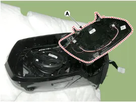
Blind Spot Detection Warning Indicator
| 1. |
Disconnect the negative (-) battery terminal. |
| 2. |
Remove the mirror (A).
|
| Installation |
Blind Spot Detection Warning Indicator
| 1. |
Install the outside mirror. |
| 2. |
Connect the negative (-) battery terminal. |
| Inspection |
Diagnosis With GDS
| 1. |
In the body electrical system, failure can be quickly diagnosed by using the vehicle diagnostic system (GDS).
The tester (GDS) provides the following information.
|
| 2. |
Select the 'Car model' and the system to be checked in order to check the vehicle with the tester. |
| 3. |
Select the module to be checked after selecting BCM.
|

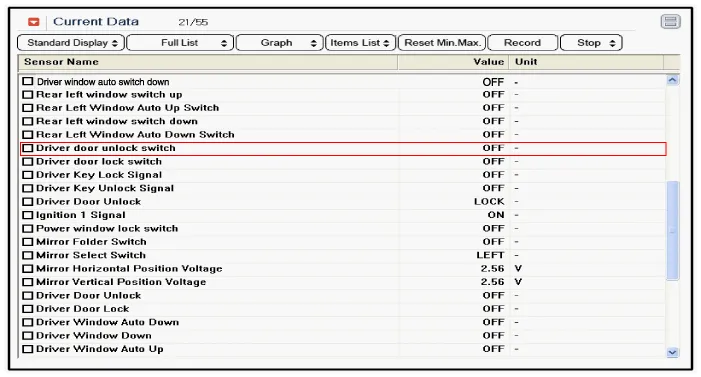
| 4. |
Select the 'Input/Output monitoring" menu to search the current state of the input/output data.
The input/output data for the sensors corresponding to the driver seat or assistant door module(DDM/ADM) can be checked.
|
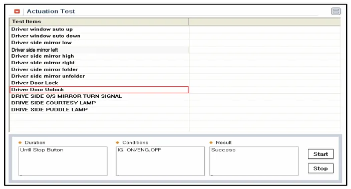
| 5. |
If you will check the power door lock operation forcefully, select "Actuation test".
|
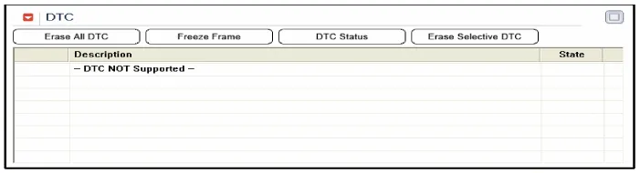
| 6. |
To check the DTC of the DDM/AMD module, select "Diagnostic trouble codes"
|
Components 1. AVM Camera2. Ambient temperature sensor3. Puddle lamp
Other information:
Hyundai Genesis (DH) 2013-2016 Service Manual: Rheostat Repair procedures
Inspection 1. Disconnect the negative (-) battery terminal. 2. Remove the crash pad lower panel. (Refer to Body - "Crash Pad Lower Panel") 3. Remove the lower crash pad switch assembly (A) after disengaging the mounting clip. 4. Remove the rheostat switch connector (A).
Hyundai Genesis (DH) 2013-2016 Service Manual: In-car Sensor Repair procedures
I
Categories
- Manuals Home
- Hyundai Genesis Owners Manual
- Hyundai Genesis Service Manual
- Electric Parking Brake (EPB) Repair procedures
- Engine Mechanical System
- Repair procedures
- New on site
- Most important about car

Copyright © 2026 www.hgenesisdh.com - 0.0221