Hyundai Genesis (DH): Engine Control System / Barometric Pressure Sensor (BPS) Schematic Diagrams
Hyundai Genesis (DH) 2013-2016 Service Manual / Engine Control / Fuel System / Engine Control System / Barometric Pressure Sensor (BPS) Schematic Diagrams
| Circuit Diagram |
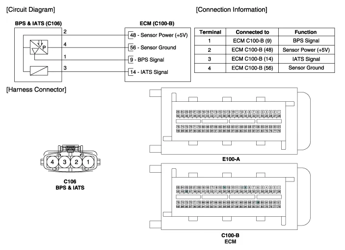
Specification Pressure (kPa)Output Voltage (V)10.00.5055.02.21100.03.93115.04.50
Inspection 1. Connect the GDS on the Data Link Connector (DLC). 2. Measure the output voltage of the BPS at idle and with the ignition ON. Specification: Refer to "Specification" Removal 1.
Other information:
Hyundai Genesis (DH) 2013-2016 Service Manual: Blind Spot Detection Indicator Repair procedures
Removal Blind Spot Detection Warning Indicator 1. Disconnect the negative (-) battery terminal. 2. Remove the mirror (A). Installation Blind Spot Detection Warning Indicator 1. Install the outside mirror. 2. Connect the negative (-) battery terminal.
Hyundai Genesis (DH) 2013-2016 Service Manual: PGS Unit (Back & Blinde Unit) Schematic Diagrams
C
Categories
- Manuals Home
- Hyundai Genesis Owners Manual
- Hyundai Genesis Service Manual
- Body (Interior and Exterior)
- Restraint
- Transmission Control Module (TCM) Repair procedures
- New on site
- Most important about car

Copyright © 2026 www.hgenesisdh.com - 0.0205