Hyundai Genesis (DH): AWD Control System / AWD ECU Flow Diagram
Hyundai Genesis (DH) 2013-2016 Service Manual / 4 Wheel Drive (AWD) System / AWD Control System / AWD ECU Flow Diagram
| AWD ECU input/output diagram |
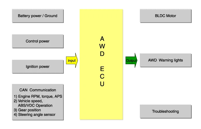
Description The AWD ECU distributes the driving force to the front/rear wheel through controlling the multi plate clutch on the AWD transfer case by analyzing the input information, i.
Circuit diagram AWD ECU connector AWD ECU terminal function 1Motor electric power2Ground connection3Ignition4-5-6CAN high7CAN low8Electric power supply controller
Categories
- Manuals Home
- Hyundai Genesis Owners Manual
- Hyundai Genesis Service Manual
- Engine Mechanical System
- General Information
- Description and Operation
- New on site
- Most important about car

Copyright © 2026 www.hgenesisdh.com - 0.0271