Hyundai Genesis (DH): Smart Cruise Control System / Smart Cruise Control Switch Schematic Diagrams
| Circuit Diagram |
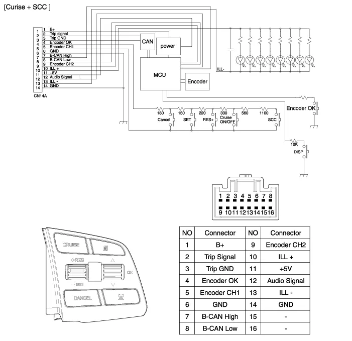
Components 1. SET - switch2. RES + switch3. SCC switch4. CANCEL switch5. CRUISE switch
Inspection [Measuring Resistance] 1. Disconnect the cruise control switch connector from the control switch. 2. Measure resistance between terminals on the control switch when each function switch is ON (switch is depressed).
Other information:
Hyundai Genesis (DH) 2013-2016 Service Manual: Description and Operation
Description System Overview The System offers the following features: - Changing the state of engine ignition and power by using the start button. - Controlling external relays for ACC / IGN1 / IGN2 terminal switching and STARTER, without use of mechanical ignition switch.
Hyundai Genesis (DH) 2013-2016 Service Manual: Photo Sensor Description and Operation
Description The photo sensor is located in the right side of the inside rearview mirror. he integrated rain sensor is located in the right side of the inside rearview mirror. The integrated rain sensor is a multifunctional sensor which combines the photo sensor and auto light sensor, and has a built-in photovoltaic diode (for detecting t
Categories
- Manuals Home
- Hyundai Genesis Owners Manual
- Hyundai Genesis Service Manual
- Starter Repair procedures
- Description and Operation
- Electric Parking Brake (EPB) Repair procedures
- New on site
- Most important about car
