Hyundai Genesis (DH): Fuses And Relays / Relay Box (Passenger Compartment) Description and Operation
| Description |
| Appellation | Description |
| AAF | Active Air Flap |
| ACU | Airbag Control Unit |
| ADM | Assist Door Module |
| AHD | Active Hood System |
| AMP | Amplifier |
| ARS | Armrest Switch |
| ASCC | Advanced Smart Cruise Control |
| AVM | Around View Monitor |
| AWD | All Wheel Drive |
| B_CAN | Body Controller Area Network |
| BCM | Body Control Module |
| BSD | Blind Spot Detection |
| C_CAN | Chassis Controller Area Network |
| CCP | Center Control Panel |
| CLUM | Cluster Module |
| DATC | Dual Automatic Temp Control |
| DDM | Driver Door Module |
| Display | Display Monitor |
| DSS | Driver Seat Switch |
| ECS | Electronic Control Suspention |
| EMS | Engine Management System |
| EPB | Electronic Parking Brake |
| EVP | Eva Vacuum Pump |
| FPCM | Fuel Pump Control Module |
| H/Unit | Head Unit |
| HSWS | Haptic Steering Warning System |
| HUD | Head Up Display |
| I-BOX | Telematics System |
| IDB | Integrated Dynamic Brake |
| LDWS | Lane Departure Warning System |
| M_CAN | Multi media Controller Area Network |
| MDPS | Motor Driven Power Steering |
| MFS | Multi-Function Switch |
| ODS | Occupant Detection System |
| P_CAN | Powertrain Controller Area Network |
| PGS | Parking Guide System |
| PSB | Pre-Safe Seat Belt |
| PSM | Power Seat Module |
| PTLM | Power Trunk Lid Module |
| RRC | Rear Remote Control |
| SAS | Steering Angle Sensor |
| SCM | Steering Column Module |
| SJB | Smart Junction Box |
| SLB | Seat Lumber Bolster |
| SMK | Smart Key Unit |
| SPAS | Smart Parking Assist System |
| SWRC | Steering Wheel Remote Controller |
| TCU | Transmission Control Unit |
| TPMS | Tire Pressure Monitoring System |
| VDC | Vehicle Dynamic Control |
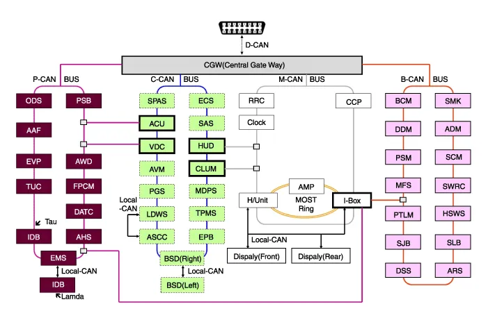
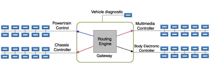
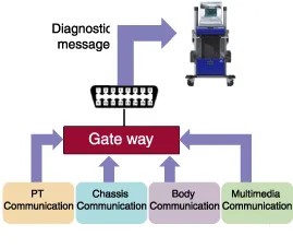
| 1. |
CGW Main Features
|

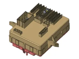
| 2. |
How to check CGW
Component Location Interior Junction Block Fuse Inspection 1. Check that the fuse holders are loosely held and that the fuses are securely fixed by the holders. 2. Check that each fuse circuit has the exact fuse capacity. Other information:Hyundai Genesis (DH) 2013-2016 Service Manual: Auto Head Lamp Leveling Unit Repair proceduresInspection 1. Ignition "ON". 2. Turn on the head lamp switch. 3. Check that the aim of the head lamp changes smoothly when the head lamp leveling device switch is turned on. 4. If it does not operate well, check the connector and terminals to make sure that they are connected. Hyundai Genesis (DH) 2013-2016 Service Manual: Compressor Repair proceduresRemoval 1. If the compressor is marginally operable, run the engine at idle speed, and let the air conditioning work for a few minutes, then shut the engine off. 2. Disconnect the negative (-) battery terminal. 3. Remove the engine room cover. Categories

Copyright © 2026 www.hgenesisdh.com - 0.0357
|