Hyundai Genesis (DH): Engine Control System / Knock Sensor (KS) Repair procedures
Hyundai Genesis (DH) 2013-2016 Service Manual / Engine Control / Fuel System / Engine Control System / Knock Sensor (KS) Repair procedures
| Removal |
| [Knock Sensor #1 (Bank 1)] |
| 1. |
Turn the ignition switch OFF and disconnect the battery negative (-) cable. |
| 2. |
Disconnect the knock sensor connector (A).
|
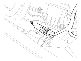
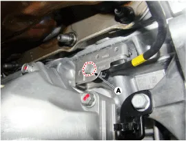
| 3. |
Remove the installation bolt (A), and then remove the sensor from the cylinder block.
|
| [Knock Sensor #2 (Bank 2)] |
| 1. |
Turn the ignition switch OFF and disconnect the battery negative (-) cable. |
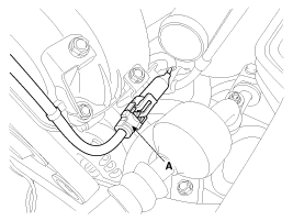
| 2. |
Disconnect the knock sensor connector (A).
|
| 3. |
Drain the engine coolant.
(Refer to Engine Mechanical System - |
Circuit Diagram
Description Heated Oxygen Sensor (HO2S) consists of zirconium and alumina and is installed on upstream and downstream of the Manifold Catalyst Converter (MCC).
Other information:
Hyundai Genesis (DH) 2013-2016 Service Manual: Description and Operation
Description BSD is a system that measures the speed of and distance from the following vehicles by using two magnetic wave radar sensors attached to the rear bumper, and detects any vehicle within the blind spot zone and gives off alarm (visual and auditory).
Hyundai Genesis (DH) 2013-2016 Service Manual: Head Up Display Unit Repair procedures
Removal 1. Disconnect the negative (-) battery terminal. 2. Remove the head up display bezel (A). 3. Remove the instrument cluster. (Refer to Indicators And Guages - "Instrument Cluster") 4. Remove the head up display unit bracket (A) after loosening the mounting nuts.
Categories
- Manuals Home
- Hyundai Genesis Owners Manual
- Hyundai Genesis Service Manual
- Front Door
- General Information
- Suspension System
- New on site
- Most important about car

Copyright © 2026 www.hgenesisdh.com - 0.0266