
Hyundai Genesis (DH): Power Door Mirrors / Power Door Mirror Switch Components and Components Location
Hyundai Genesis (DH) 2013-2016 Service Manual / Body Electrical System / Power Door Mirrors / Power Door Mirror Switch Components and Components Location
| Components |
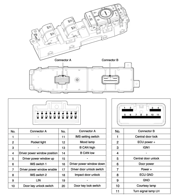
Component Location 1. Power door mirror2. Power door mirror switch3. Power folding mirror switch
Circuit Diagram
Other information:
Hyundai Genesis (DH) 2013-2016 Service Manual: License Lamps Repair procedures
Removal 1. Disconnect the negative (-) battery terminal. 2. Remove the trunk lid panel. (Refer to Body - "Trunk Lid Back Panel") 3. Remove the license lamp after disengaging the license lamp mounting clip (A) 4. Remove the license lamp assembly after disconnecting the license connector (A).
Hyundai Genesis (DH) 2013-2016 Service Manual: Photo Sensor Repair procedures
Inspection 1. Turn the ignition switch ON. 2. Connect the GDS. 3. Emit intensive light toward the photo sensor using a lamp, and check the output voltage change. 4. The voltage will rise with higher intensive light and fall with lower intensive light.
Categories
- Manuals Home
- Hyundai Genesis Owners Manual
- Hyundai Genesis Service Manual
- 4 Wheel Drive (AWD) System
- Suspension System
- Electric Parking Brake (EPB) Repair procedures
- New on site
- Most important about car

Copyright В© 2026 www.hgenesisdh.com - 0.0322