Hyundai Genesis (DH): General Information / General Service Information
Hyundai Genesis (DH) 2013-2016 Service Manual / General Information / General Service Information
General Information
| General Service Information |
Protection of the Vehicle
Always be sure to cover fenders, seats, and floor areas prior to beginning work.
The support rod must be inserted into the hole near the edge
of the hood whenever you inspect the engine compartment to prevent the
hood from falling and causing possible injury.
Make sure that the support rod has been released prior to
closing the hood. Always make sure the hood is firmly latched before
driving the vehicle. |

Preparation of Tools and Measuring Equipment
Make sure that all necessary tools and measuring equipment are available prior to beginning work.
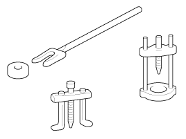
Special Tools
Use special tools when they are required.
Removal of Parts
First find the cause of the problem and then determine whether removal of disassembly is needed before starting the job.
Disassembly
If the disassembly procedure is so complex that it requires
many parts to be disassembled, all parts should be disassembled in a way
that will not affect their performance or external appearance.
| 1. |
Inspection of parts
Each part, when removed, should be carefully inspected for malfunction, deformation, damage, and other problems.
|

| 2. |
Arrangement of parts
All disassembled parts should be carefully arranged for effective reassembly.
Be sure to separate and distinguish the parts to be replaced from those that will be used again.
|
| 3. |
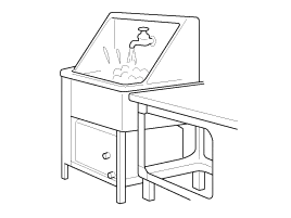
Cleaning parts for reuse
All parts to be used again should be carefully and thoroughly cleaned in an appropriate method.
|
Parts
When replacing parts, use HYUNDAI genuine parts.
Replacement
Standard values, such as torques and certain adjustments, must be strictly observed in the reassembly of all parts.
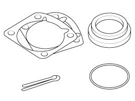
If removed, the following parts should always be replaced with new ones.
| 1. |
Oil seals |
| 2. |
Gaskets |
| 3. |
O-rings |
| 4. |
Lock washers |
| 5. |
Cotter pins (split pins) |
| 6. |
Plastic nuts
Depending on their location. |
| 7. |
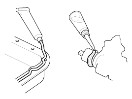
Sealant should be applied to gaskets. |
| 8. |
Oil should be applied to the moving components of parts. |
| 9. |
Specified oil or grease should be applied to the prescribed locations (oil seals, etc.) before assembly.
|
Adjustment
Use gauges and testers to adjust correctly the parts to standard values.
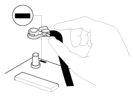
Electrical System
| 1. |
Be sure to disconnect the battery cable from the negative (-) terminal of the battery. |
| 2. |
Never pull on the wires when disconnecting connectors. |
| 3. |
Locking connectors will click when the connector is secure. |
| 4. |
Handle sensors and relays carefully. Be careful not to drop them against other parts.
|
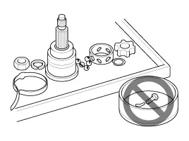
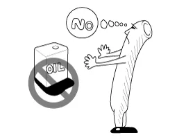
Rubber Parts and Tubes
Always prevent gasoline or oil from contacting the rubber parts or tubes.
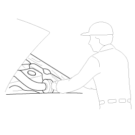
Measuring Body Dimensions
| 1. |
Basically, all measurements in this manual are taken with a tracking gauge. |
| 2. |
When a measuring tape is used, check to be sure there is no elongation, twisting or bending. |
| 3. |
For measuring dimensions, both projected dimensions and actual - measurement dimensions are used in this manual. |
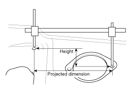
Projected Dimensions
| 1. |
The dimensions are measured by projecting the measurement points on the vehicle surface onto the reference dimensions. |
| 2. |
If the length of the tracking gauge proves is adjustable,
measure the dimensions by lengthening one of the two probes to the
height difference between the two measuring surfaces.
|
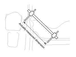
Measuring Actual Dimensions
| 1. |
These dimensions indicate the actual linear distance between
measurement points, and are used as the reference dimensions when a
tracking gauge is used for measurement. |
| 2. |
First adjust both probes to the same length (A=A') before measurement.
|

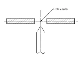
Measurement Point
Measurements should be taken at the center of the hole.
Checking Cables and Wires
| 1. |
Check the terminal for tightness. |
| 2. |
Check terminals and wires for corrosion from battery electrolyte, etc. |
| 3. |
Check terminals and wires for open circuits. |
| 4. |
Check wire insulation and coating for damage, cracks and degrading. |
| 5. |
Check whether the conductive parts of terminals contact other metallic parts (vehicle body and other parts). |
| 6. |
Check whether there is complete continuity between the attaching bolt(s) of the grounded parts and the vehicle |
General Information Basic Service Symbols There are five primary symbols used to complement illustrations. These symbols indicated the materials to be applied to parts during service.
Other information:
Hyundai Genesis (DH) 2013-2016 Service Manual: Ambient Temperature Sensor Description and Operation
Description The ambient temperature sensor is located inside the side mirror and detects ambient air temperature. It is a negative type thermistor; resistance will increase with lower temperature, and decrease with higher temperature. The sensor output will be used for discharge temperature control, temperature regulation door control,
Hyundai Genesis (DH) 2013-2016 Service Manual: Blower Unit Repair procedures
R
Categories
- Manuals Home
- Hyundai Genesis Owners Manual
- Hyundai Genesis Service Manual
- Repair procedures
- Steering System
- Smart Cruise Control Unit Repair procedures
- New on site
- Most important about car

Copyright © 2026 www.hgenesisdh.com - 0.0271