Hyundai Genesis (DH): Engine Control System / Accelerator Position Sensor (APS) Schematic Diagrams
Hyundai Genesis (DH) 2013-2016 Service Manual / Engine Control / Fuel System / Engine Control System / Accelerator Position Sensor (APS) Schematic Diagrams
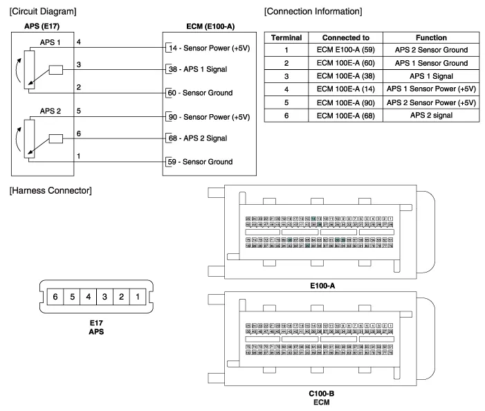
| Circuit Diagram |
Specification AcceleratorPositionOutput Voltage (V)APS1APS2C.T0.7 ~ 0.80.33 ~ 0.43W.O.T3.85 ~ 4.351.93 ~ 2.18
Inspection 1. Connect the GDS on the Data Link Connector (DLC). 2. Turn the ignition switch ON. 3. Measure the output voltage of the APS 1 and 2 at C.
Categories
- Manuals Home
- Hyundai Genesis Owners Manual
- Hyundai Genesis Service Manual
- 4 Wheel Drive (AWD) System
- General Information
- Engine Electrical System
- New on site
- Most important about car

Copyright © 2026 www.hgenesisdh.com - 0.0211