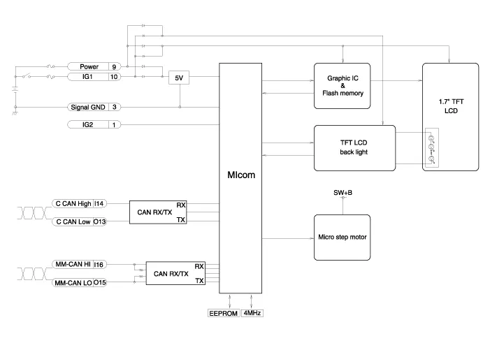
Hyundai Genesis (DH): Head Up Display System / Head Up Display Unit Schematic Diagrams
Hyundai Genesis (DH) 2013-2016 Service Manual / Body Electrical System / Head Up Display System / Head Up Display Unit Schematic Diagrams
| Circuit Diagram |
Removal 1. Disconnect the negative (-) battery terminal. 2. Remove the head up display bezel (A). 3. Remove the instrument cluster. (Refer to Indicators And Guages - "Instrument Cluster") 4.
Other information:
Hyundai Genesis (DH) 2013-2016 Service Manual: Auto Light Sensor Repair procedures
Removal 1. Disconnect the negative (-) battery terminal. 2. Remove the photo & auto light sensor. (Refer to Windshield Wiper/Washer - "Rain Sensor") Installation 1. Install the auto light sensor. 2. Connect the negative (-) battery terminal.
Hyundai Genesis (DH) 2013-2016 Service Manual: Description and Operation
Description Control Function This system supports 2 kinds of main function. (Rear video display function, Expected trace of wheels display function) The Rear video display and the expected trace of wheels display operate according to Vehicle speed condition and Gear position.
Categories
- Manuals Home
- Hyundai Genesis Owners Manual
- Hyundai Genesis Service Manual
- Description and Operation
- Body (Interior and Exterior)
- Smart Cruise Control Unit Repair procedures
- New on site
- Most important about car

Copyright © 2026 www.hgenesisdh.com - 0.0313