Hyundai Genesis (DH): Body Dimensions / General Information
| General |
| 1. |
Basically, all measurements in this manual are taken with a tracking gauge. |
| 2. |
When a measuring tape is used, check to be sure there is no elongation, twisting or bending. |
| 3. |
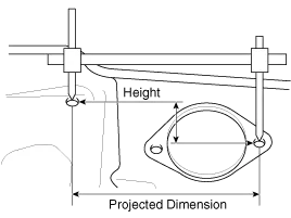
For measuring dimensions, both projected dimension and actual-measurement dimension are used in this manual. |
| Measurement Method |
| Projected Dimensions |
| 1. |
These are the dimensions measured when the measurement
points are projected into the reference plane, and are the reference
dimensions used for body alterations. |
| 2. |
If the length of the tracking gauge probes is adjustable,
make the measurement by lengthening one probe by the amount equivalent
to the difference in height of the two surfaces.
|
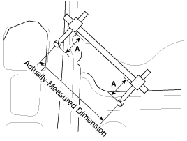
| Actual-Measurement Dimensions |
| 1. |
These dimensions indicate the actual linear distance between
measurement points, and are the reference dimensions for use if a
tracking gauge is used for measurement. |
| 2. |
Measure by first adjusting both probes to the same length (A=A').
|

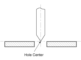
| Measurement Point |
| 1. |
Measurements should be taken at the hole center.
|
Front Body A * These dimensions indicated in this figure are actual-measurement dimensions. [ Unit : mm (inch) ] Front Body B * These dimensions indicated in this figure are actual-measurement dimensions.
Other information:
Hyundai Genesis (DH) 2013-2016 Service Manual: Auto Light Sensor Repair procedures
Removal 1. Disconnect the negative (-) battery terminal. 2. Remove the photo & auto light sensor. (Refer to Windshield Wiper/Washer - "Rain Sensor") Installation 1. Install the auto light sensor. 2. Connect the negative (-) battery terminal.
Hyundai Genesis (DH) 2013-2016 Service Manual: General Safety Information and Caution
Instructions When Handling Refrigerant 1. R-134a liquid refrigerant is highly volatile. A drop on the skin of your hand could result in localized frostbite. When handling the refrigerant, be sure to wear gloves. 2. It is standard practice to wear goggles or glasses to protect your eyes, and gloves to protect your hands.
Categories
- Manuals Home
- Hyundai Genesis Owners Manual
- Hyundai Genesis Service Manual
- Transmission Control Module (TCM) Repair procedures
- Parking Assist Sensor Repair procedures
- Repair procedures
- New on site
- Most important about car
