Hyundai Genesis: Power Door Locks / Description and Operation

Description
System Overview
The larger the size of the door, the harder it is to close it. Quite often we see people driving with a door not completely closed.
Power door latch addresses the issue of partially completely closes the doors partially shut if the driver/passenger gives a little push to them.
Commonly, partial door closure is known as 1st closure and full door closure is known as 2nd closure.
Main features of the system are as follows.
-
Featured on all four doors.
-
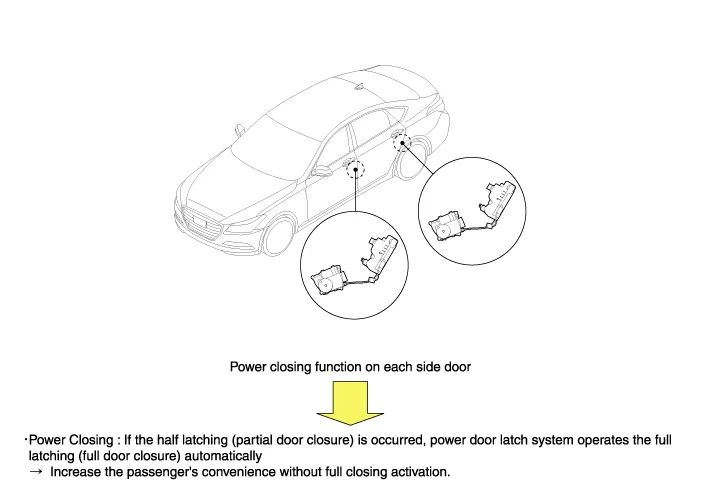
Consists of a door lock actuator and a soft closing actuator.
-
Locks/unlocks doors using DDM and ADM signals.

System Structure
Following is a diagram of the driver’s side door lock and power latch units.
DDM detects and controls the state of power and switch (lock/unlock switch, door key switch) of power door latch lock/unlock activation, and power latch function is independently operated.

Latch & Actuator
Known collectively as the door lock actuator and as the part where the striker lands when the door is closed.
1.
Latch
Identical in design to conventional latches and contains an SCA cable that supplies the power needed to close partially closed doors.
2.
Actuator
Contains a door lock/unlock control motor, a lock/unlock detection switch, and a door key detection switch. Power door latch actuators also feature a pawl switch and an ajar switch that communicate with SCA.
SCA (Soft Closing Actuator)
SCA utilizes its Power Closing motor to completely close partially closed doors.
1.
ECU
ECU controls SCA by monitoring the ajar and pawl switches and determining whether to operate the power latch feature ECU is built on a PCB inside SCA.
2.
Power Closing Motor
Upon receiving a signal from the ECU, the Power Closing motor rotates to pull the door shut and then rewinds to standby for the next activation signal.
3.
Hall Sensor
The hall sensor is mounted to the PCB and determines the power latch’s initial position by sensing the location of a magnet that’s attached to the gear.
Power Door Latch Switch
The power door latch feature must first determine if the door is completely shut or partially shut. This is accomplished by a switch located inside the latch (door lock actuator) and a body electrical switch.
1.
Ajar Switch
The word "ajar" means slightly open, and the ajar switch determines whether the striker has completely engaged the latch when the door is shut. This switch is mounted inside the door latch and is triggered by an internal link. The switch’s function reaches a full cycle as the signal shifts from On to Off.
And, because the switch is mounted inside the actuator, it’s not possible to inspect the switch individually.
To perform a test, use the external connector and measure the voltage change.
2.
Pawl Switch
The pawl switch is triggered when the door is partially shut. The power door latch function turns off when the switch OFF signal is transmitted.
Like the ajar switch, the pawl switch is installed inside the actuator and must also be tested for voltage change using the external connector.
3.
Ajar & Pawl Switch Activation
These switches have the following activation scheme:
Switch
Door Ajar
Door Closing
Door Closed
Ajar Switch
ON
ON
OFF
Pawl Switch
ON
OFF > ONInternal link changes the contact status.
OFF
Power Latch
Inactive
Active
Terminated

Components and Components Location
Component Location 1. DDM (Driver Door Module)2. ADM (Assist Door Module)3. IGPM (Integrated Gateway Power Control Module)4. Door lock knob5. Trunk lid actuator6. Front soft closing actuator (SCA ...

Power Door Lock Actuators Components and Components Location
Components 1. Power Actuator2. Cinching Cable3. Door Latch ...

Other information:

Hyundai Genesis (DH) 2013-2016 Service Manual: Purge Control Solenoid Valve (PCSV) Specifications


Specification ItemSpecificationCoil Resistance (?)22.0 ~ 26.0 [20°C(68°F)] ...

Hyundai Genesis (DH) 2013-2016 Service Manual: Smart Cruise Control Switch Repair procedures


Inspection [Measuring Resistance] 1. Disconnect the cruise control switch connector from the control switch. 2. Measure resistance between terminals on the control switch when each function switch is ON (switch is depressed). Function switchTerminalResistance (k?)SET -5 - 60.31 ~ 0.35 ...

© 2013-2024 www.hgenesisdh.com