
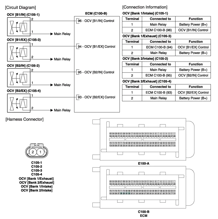
Hyundai Genesis (DH): Engine Control System / CVVT Oil Control Valve (OCV) Schematic Diagrams
Hyundai Genesis (DH) 2013-2016 Service Manual / Engine Control / Fuel System / Engine Control System / CVVT Oil Control Valve (OCV) Schematic Diagrams
| Circuit Diagram |
Signal Waveform
Inspection 1. Turn the ignition switch OFF. 2. Disconnect the OCV connector. 3. Measure resistance between the OCV terminals 1 and 2. 4.
Other information:
Hyundai Genesis (DH) 2013-2016 Service Manual: Start/Stop Button Repair procedures
Removal 1. Disconnect the negative(-) battery terminal. 2. Remove the driver crash pad lower panel. (Refer to Body - "Crash Pad Lower Panel") 3. Remove the start/stop button (A) from the center fascia garnish after loosening the mounting clip.
Hyundai Genesis (DH) 2013-2016 Service Manual: Specifications
S
Categories
- Manuals Home
- Hyundai Genesis Owners Manual
- Hyundai Genesis Service Manual
- Transmission Control Module (TCM) Repair procedures
- Emission Control System
- Description and Operation
- New on site
- Most important about car

Copyright В© 2026 www.hgenesisdh.com - 0.0328