Hyundai Genesis: Cylinder Head Assembly / Camshaft Repair procedures

Removal
LH Intake and Exhaust camshaft
1.
Remove the timing chain.
(Refer to Timing System - "Timing Chain")
2.
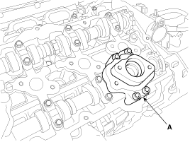
Remove the fuel pump bracket (A).

3.
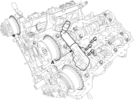
Remove the LH exhaust camshaft oil control valve (OCV) (A).
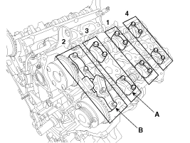
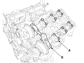
4.
Remove the LH camshaft bearing cap (A) and thrust bearing cap (B).
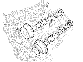
5.
Remove the LH camshaft assembly (A).

RH Intake and Exhaust camshaft
1.
Remove the timing chain.
(Refer to Timing System - "Timing Chain")
2.
Remove the RH exhaust camshaft oil control valve (OCV) (A).
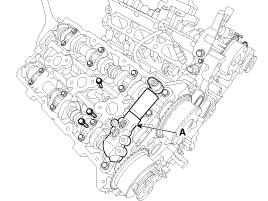
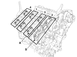
3.
Remove the RH camshaft bearing cap (A) and thrust bearing cap (B).
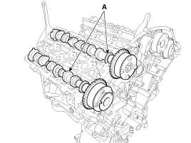
4.
Remove the RH camshaft assembly (A).

Inspection
1.
Inspect cam lobes.
Using a micrometer, measure the cam lobe height.

Cam height
[Standard value]
Intake : 47.2 mm (1.8582 in.)
Exhaust : 45.8 mm (1.8031 in.)

If the cam lobe height is less than standard, replace the camshaft.
2.
Check the surface of the camshaft journal for wear.
If the journal is worn excessively, replace the camshaft.
3.
Inspect the camshaft journal clearance.
(1)
Clean the bearing caps and camshaft journals.
(2)
Place the camshafts on the cylinder head.
(3)
Lay a strip of plastigage across each of the camshaft journals.

(4)
Install the bearing cap (A) and thrust bearing cap (B) with specified torque.

Tightening torque :
1st step : 5.8 N.m (0.6 kgf.m, 4.3 lb-ft)
2nd step :
9.8 ~ 11.8 N.m (1.0 ~ 1.2 kgf.m, 7.2 ~ 8.7 lb-ft)

   
Do not turn the camshaft.
Be careful not to mistake the thrust bearing cap (B) bolt for a common bearing cap (A) bolt.
(5)
Remove the bearing caps.
(6)
Measure the width of the plastigage at its widest point.

Bearing oil clearance
[Standard value]
Intake
No.1 journal : 0.027 ~ 0.057 mm (0.0010 ~ 0.0022 in.)
No.2,3,4 journal :
0.030 ~ 0.067 mm (0.0012 ~ 0.0026 in.)
Exhaust
No.1 journal : 0.027 ~ 0.057 mm (0.0010 ~ 0.0022 in.)
No.2,3,4 journal :
0.030 ~ 0.067 mm (0.0012 ~ 0.0026 in.)

A.
If the oil clearance is greater than specification, replace the camshaft.
B.
If the oil clearance is still greater than specification after camshaft replacement, replace the bearing caps and cylinder head a set .
(7)
Completely remove the plastigage.
(8)
Remove the camshafts.
4.
Inspect the camshaft end play.
(1)
Install the camshafts.
(2)
Install the bearing cap (A) and thrust bearing cap (B) with specified torque.

Tightening torque :
1st step : 5.8 N.m (0.6 kgf.m, 4.31 lb-ft)
2st step : 9.8 N.m (1.0 ~ 1.2 kgf.m, 7.2 ~ 8.7 lb-ft)

   
Do not turn the camshaft.
Be careful not to mistake the thrust bearing cap (B) bolt for a common bearing cap (A) bolt.
(3)
Using a dial gauge, measure the end play while moving the camshaft back and forth.

Camshaft end play
[Standard value] :
0.02 ~ 0.18 mm (0.0008 ~ 0.0071 in.)

A.
If the end play is greater than specification, replace the camshaft.
B.
If the end play is still greater than specification after camshaft replacement, replace the bearing caps and cylinder head as a set.
(4)
Remove the camshafts.
Installation
   
Be careful when assembling the right/left bank, intake/exhaust side.
Assemble the key groove of camshaft rear side to the same level of head top surface.
Apply a light coat of engine oil on camshaft journals.
[Intake camshaft]

As for camshaft identification, refer to the table below.
Displacement
Left Bank
Right Bank
3.8L
A : 27mm (1.0630in.)
B : 27mm (1.0630in.)
C : 30mm (1.1811in.)
D : 30mm (1.1811in.)
E : 27mm (1.0630in.)
A : 27mm (1.0630in.)
B : 27mm (1.0630in.)
C : 30mm (1.1811in.)
D : 27mm (1.0630in.)
E : 30mm (1.1811in.)

[Exhaust Camshaft]

As for camshaft identification, refer to the table below.
Displacement
Left Bank
Right Bank
3.8L
A : -
B : -
C : -
D : -
E : 31mm (1.2205in.)
A : 27mm (1.0630in.)
B : 27mm (1.0630in.)
C : 30mm (1.1811in.)
D : 30mm (1.1811in.)
E : -

LH Intake and Exhaust camshaft
1.
Install the LH camshaft assembly (A).

2.
Install the LH camshaft bearing cap (A) and thrust bearing cap (B).

Tightening torque
1st step : 5.8 N.m (0.6 kgf.m, 4.3 lb-ft)
2nd step :
9.8 ~ 11.8 N.m (1.0 ~ 1.2 kgf.m, 7.2 ~ 8.7 lb-ft)

   
Be sure to install the thrust bearing cap bolts and the bearing cap bolts in the correct place.
   
Be careful when assembling the right/left bank, intake/exhaust side.

A : L(LH),R(RH)
B : I(Intake), E(Exhaust)
C : Journal number
D : Front mark
   
When assembling the camshaft bearing cap, rotate the crankshaft to locate the pistons at the center of the cylinder block in order to avoid unnecessary contact between the valves and pistons.
3.
Install the LH exhaust camshaft oil control valve (OCV) (A).
(Refer to Engine Control/Fuel System - "CVVT Oil Control Valve (OCV)")

Tightening torque :
9.8 ~ 11.8 N.m (1.0 ~ 1.2 kgf.m, 7.2 ~ 8.7 lb-ft)

4.
Install the fuel pump bracket (A).

Tightening torque :
18.6 ~ 23.5 N.m (1.9 ~ 2.4 kgf.m, 13.7 ~ 17.4 lb-ft)

5.
Install the timing chain.
(Refer to Timing System - "Timing Chain")
RH Intake and Exhaust camshaft
1.
Install the RH camshaft assembly (A).

2.
Install the RH camshaft bearing cap (A) and thrust bearing cap (B).

Tightening torque
1st step : 5.8 N.m (0.6 kgf.m, 4.3 lb-ft)
2nd step :
9.8 ~ 11.8 N.m (1.0 ~ 1.2 kgf.m, 7.2 ~ 8.7 lb-ft)

   
Be sure to install the thrust bearing cap bolts and the bearing cap bolts in the correct place.
   
Install the bearing caps in their correct position, being careful of the mark shown below.

A : L(LH),R(RH)
B : I(Intake), E(Exhaust)
C : Journal number
D : Front mark
   
When assembling the camshaft bearing cap, rotate the crankshaft to locate the pistons at the center of the cylinder block in order to avoid unnecessary contact between the valves and pistons.
3.
Install the RH exhaust camshaft oil control valve (OCV) (A).

Tightening torque :
9.8 ~ 11.8 N.m (1.0 ~ 1.2 kgf.m, 7.2 ~ 8.7 lb-ft)

4.
Install the timing chain.
(Refer to Timing System - "Timing Chain")
Camshaft Components and Components Location
Components 1. RH Exhaust camshaft2. RH Intake camshaft3. LH Intake camshaft4. LH Exhaust camshaft ...

Cylinder Head Components and Components Location
Components 1. RH intake camshaft OCV2. Camshaft thrust bearing cap 3. Camshaft bearing cap 4. RH exhaust camshaft5. RH intake camshaft6. RH exhaust camshaft CVVT assembly7. RH intake camshaft CVV ...

Other information:

Hyundai Genesis (DH) 2013-2016 Service Manual: Steering Wheel Remote Controller (SWRC) Schematic Diagrams


Circuit Diagram ...

Hyundai Genesis (DH) 2013-2016 Owners Manual: Side curtain


To use the side curtain: 1. Lift the curtain by the hook (1). 2. Hang the curtain on both sides of the hook. CAUTION Always hang both sides of the curtain on the hook. This could cause damage to the side curtain if only one side of the curtain is hooked. Do not let any forei ...

© 2013-2024 www.hgenesisdh.com