Hyundai Genesis (DH): Engine Control System / Accelerator Position Sensor (APS) Specifications
Hyundai Genesis (DH) 2013-2016 Service Manual / Engine Control / Fuel System / Engine Control System / Accelerator Position Sensor (APS) Specifications
| Specification |
| Accelerator Position | Output Voltage (V) | |
| APS1 | APS2 | |
| C.T | 0.7 ~ 0.8 | 0.33 ~ 0.43 |
| W.O.T | 3.85 ~ 4.35 | 1.93 ~ 2.18 |
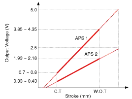
Description Accelerator Position Sensor (APS) is installed on the accelerator pedal module and detects the rotation angle of the accelerator pedal.
Circuit Diagram
Other information:
Hyundai Genesis (DH) 2013-2016 Service Manual: Repair procedures
Diagnosis With GDS 1. BSD system defects can be quickly diagnosed with the GDS. GDS operates actuator quickly to monitor, input/output value and self diagnosis. 2. Connect the cable of GDS to the data link connector in driver side crash pad lower panel, and turn on the GDS.
Hyundai Genesis (DH) 2013-2016 Service Manual: Blower Motor Repair procedures
Inspection 1. Connect the battery voltage and check the blower motor rotation. 2. If the blower motor does not operate well, replace it with a genuine blower motor check for proper operation. 3. Replace the blower motor if it is proved that there is a problem with it.
Categories
- Manuals Home
- Hyundai Genesis Owners Manual
- Hyundai Genesis Service Manual
- Active Air Flap(AAF) Repair procedures
- Electric Parking Brake (EPB) Repair procedures
- Starter Repair procedures
- New on site
- Most important about car

Copyright © 2026 www.hgenesisdh.com - 0.0232