Hyundai Genesis (DH): Premium AVN System / AVN Antenna Repair procedures
Hyundai Genesis (DH) 2013-2016 Service Manual / Body Electrical System / Premium AVN System / AVN Antenna Repair procedures
| Inspection |
Glass Antenna Test
| 1. |
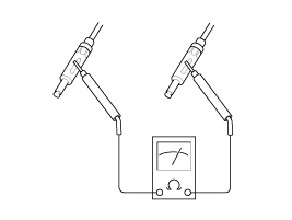
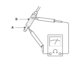
Wrap aluminum foil (A) around the tip of the tester probe (B)
and move the probe along the grid line to check whether the circuit
opens.
|
| 2. |
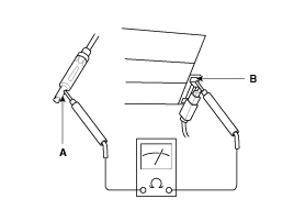
Bring one end of the tester probe into contact with the glass
antenna terminal (A) while moving the other end along the antenna wires
to check for continuity.
|
Glass Antenna Repair
To make an effective repair, the broken section must be no longer than one inch. |

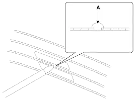
| 1. |
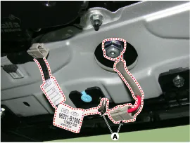
Lightly rub the area around the broken section (A) with fine
steel wool, and then clean it with alcohol with the masking tape
attached as shown below.
|
| 2. |
Mix conductive paint with thinner and apply the mixture three times at an interval of 15 minutes. |
| 3. |
Before supplying power, take the masking tape off. For a
refined finish, remove the extra paint with a knife after the paint
dries up (for about 1 day).
|
| 4. |
Check for continuity in the repaired wire. |
Glass Antenna Circuit Inspection
| 1. |
Remove the right rear quarter trim glass antenna, and then disconnect the power wiring from the amplifier. |
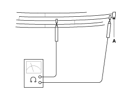
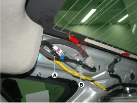
| 2. |
Turn the radio ON.
Measure the voltage between terminal 2 of the harness side feeder cable (A) and body ground (B).
|
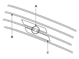
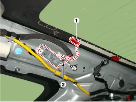
| 3. |
Using the tester, measure the wiring resistance value of AM between 1 and 2.
|
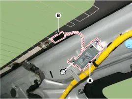
| 4. |
Using the tester, measure the wiring resistance value of FM between A and B.
|
| 5. |
Check the grid lines for continuity. |
| 6. |
In case that radio reception is poor even after the circuit inspection, replace the glass antenna amp.
If reception quality is not improved, check the radio cable and audio unit. |
Antenna Cable
| 1. |
Check for continuity between the center poles of antenna cable.
|
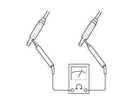
| 2. |
Check for continuity between the outer poles of antenna cable. There should be continuity.
|
| 3. |
If there is no continuity, replace the antenna cable. |
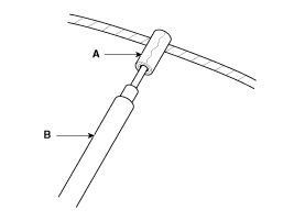
| 4. |
Check for continuity between the center pole (A) of antenna cable and terminal of glass antenna (B). There should be continuity.
|
| 5. |
If there is no continuity, replace the antenna amplifier. |
| 6. |
Check for continuity between the center pole (A) and outer pole (B) of antenna cable. There should be no continuity.
|
| 7. |
If there is continuity, replace the antenna cable. |
| Removal |
| 1. |
Disconnect the negative (-) battery terminal. |
| 2. |
Remove the roof trim.
(Refer to Body - "Roof Trim Assembly") |
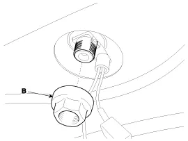
| 3. |
Remove the roof antenna (A) after loosening a nut (B).
|
| Installation |
| 1. |
Connect the roof antenna connectors. |
| 2. |
Install the rear roof trim.
|
Inspection Troubleshooting of the speakers When handling the speakers: - Do not cause shock to the speakers by dropping or throwing them.
Other information:
Hyundai Genesis (DH) 2013-2016 Service Manual: Refrigerant Line Repair procedures
Replacement 1. Discharge refrigerant from refrigeration system. 2. Replace any faulty tubes or hoses. Cap the open fittings immediately to keep moisture or dirt out of the system. 3. Tighten the bolt or nut joint to the specified torque.
Hyundai Genesis (DH) 2013-2016 Service Manual: CO2 Sensor Description and Operation
Description This system maintains the density of carbon dioxide constantly in vehicle interior by measuring the amount of carbon dioxide to increase the comfortableness and the fuel consumption rate when air conditioning system is operating.
Categories
- Manuals Home
- Hyundai Genesis Owners Manual
- Hyundai Genesis Service Manual
- General Information
- Active Air Flap(AAF) Repair procedures
- Engine Electrical System
- New on site
- Most important about car

Copyright © 2026 www.hgenesisdh.com - 0.0249